Understanding Kubernetes Networking: Pods, Services and Ingress
Originally published by Mark Betz at https://medium.com
This post is going to attempt to demystify the several layers of networking operating in a kubernetes cluster. Kubernetes is a powerful platform embodying many intelligent design choices, but discussing the way things interact can get confusing: pod networks, service networks, cluster IPs, container ports, host ports, node ports… I’ve seen a few eyes glaze over. We mostly talk about these things at work, cutting across all layers at once because something is broken and someone wants it fixed. If you take it a piece at a time and get clear on how each layer works it all makes sense in a rather elegant way.
In order to keep things focused I’m going to split the post into three parts. This first part will look at containers and pods. The second will examine services, which are the abstraction layer that allows pods to be ephemeral. The last post will look at ingress and getting traffic to your pods from outside the cluster. A few disclaimers first. This post isn’t intended to be a basic intro to containers, kubernetes or pods. To learn more about how containers work see this overview from Docker. A high level overview of kubernetes can be found here, and an overview of pods specifically is here. Lastly a basic familiarity with networking and IP address spaces will be helpful.

Understanding Kubernetes Networking: Pods
So what is a pod? A pod consists of one or more containers that are collocated on the same host, and are configured to share a network stack and other resources such as volumes. Pods are the basic unit Kubernetes applications are built from. What does “share a network stack” actually mean? In practical terms it means that all the containers in a pod can reach each other on localhost. If I have a container running nginx and listening on port 80 and another container running scrapyd the second container can connect to the first as http://localhost:80. But how does that really work? Lets look at the typical situation when we start a docker container on our local machine:
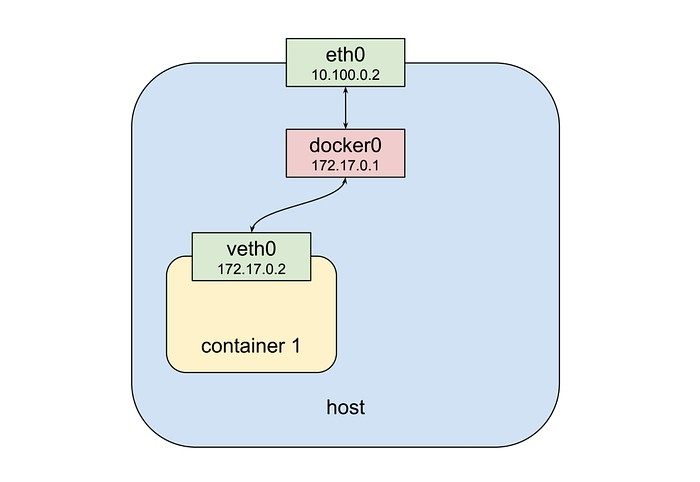
From the top down we have a physical network interface eth0. Attached to that is a bridge docker0, and attached to that is a virtual network interface veth0. Note that docker0 and veth0 are both on the same network, 172.17.0.0/24 in this example. On this network docker0 is assigned 172.17.0.1 and is the default gateway for veth0, which is assigned 172.17.0.2. Due to how network namespaces are configured when the container is launched processes inside it see only veth0, and communicate with the outside world through docker0 and eth0. Now let’s launch a second container:
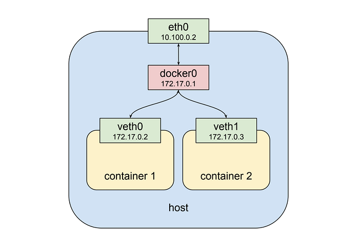
As shown above the second container gets a new virtual network interface veth1, connected to the same docker0 bridge.* This interface is assigned 172.17.0.3, so it is on the same logical network as the bridge and the first container, and both containers can communicate through the bridge as long as they can discover the other container’s IP address somehow.
[ * Dan Nissenbaum pointed out that this description omits some detail. For background see our brief discussion at the end of the post.]
[ * 12/15/2018: my previous update really got the lower levels of this wrong. The connection between a container and the bridge is established over a pair of linked virtual ethernet devices, one in the container network namespace and the other in the root network namespace. For a great overview of this subject see Kristen Jacobs’ awesome “Container Networking From Scratch” talk given this week at Kubecon 2018 in Seattle (slide link at the bottom). I really enjoyed Kristen’s presentation and I plan to shamelessly copy it in a future post on container networking.]
That’s fine and all but it doesn’t get us to the “shared network stack” of a kubernetes pod. Fortunately namespaces are very flexible. Docker can start a container and rather than creating a new virtual network interface for it, specify that it shares an existing interface. In this case the drawing above looks a little different:
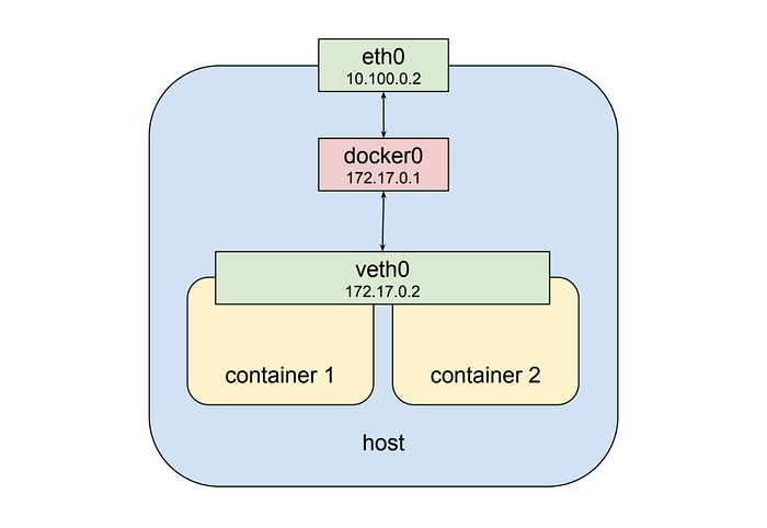
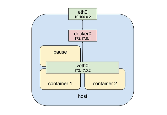
Now the second container sees veth0 rather than getting its own veth1 as in the previous example. This has a few implications: first, both containers are addressable from the outside on 172.17.0.2, and on the inside each can hit ports opened by the other on localhost. This also means that the two containers cannot open the same port, which is a restriction but no different than the situation when running multiple processes on a single host. In this way a set of processes can take full advantage of the decoupling and isolation of containers, while at the same time collaborating together in the simplest possible networking environment.
Kubernetes implements this pattern by creating a special container for each pod whose only purpose is to provide a network interface for the other containers. If you ssh in to a kubernetes cluster node that has pods scheduled on it and run docker ps you will see at least one container that was started with the pause command. The pause command suspends the current process until a signal is received so these containers do nothing at all except sleep until kubernetes sends them a SIGTERM. Despite this lack of activity the “pause” container is the heart of the pod, providing the virtual network interface that all the other containers will use to communicate with each other and the outside world. So in a hypothetical pod-like thing the last picture sort of looks like this:
The Pod Network
That’s all pretty cool, but one pod full of containers that can talk to each other does not get us a system. For reasons that will become even clearer in the next post where I discuss services, the very heart of kubernetes’ design requires that pods be able to communicate with other pods whether they are running on the same local host or separate hosts. To look at how that happens we need to step up a level and look at nodes in a cluster. This section will contain some unfortunate references to network routing and routes, a subject I realize all of humanity would prefer to avoid. Finding a clear, brief tutorial on IP routing is difficult, but if you want a decent review wikipedia’s article on the topic isn’t horrible.
A kubernetes cluster consists of one or more nodes. A node is a host system, whether physical or virtual, with a container runtime and its dependencies (i.e. docker mostly) and several kubernetes system components, that is connected to a network that allows it to reach other nodes in the cluster. A simple cluster of two nodes might look like this:
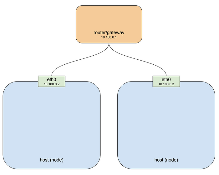
If you’re running your cluster on a cloud platform like GCP or AWS that drawing pretty well approximates the default networking architecture for a single project environment. For the purposes of illustration I’ve used the private network 10.100.0.0/24 for this example, so the router is 10.100.0.1 and the two instances are 10.100.0.2 and 10.100.0.3 respectively. Given this setup each instance can communicate with the other on eth0. That’s great, but recall that the pod we looked at above is not on this private network: it’s hanging off a bridge on a different network entirely, one that is virtual and exists only on a specific node. To make this clearer let’s drop our pod-like things back into the picture:
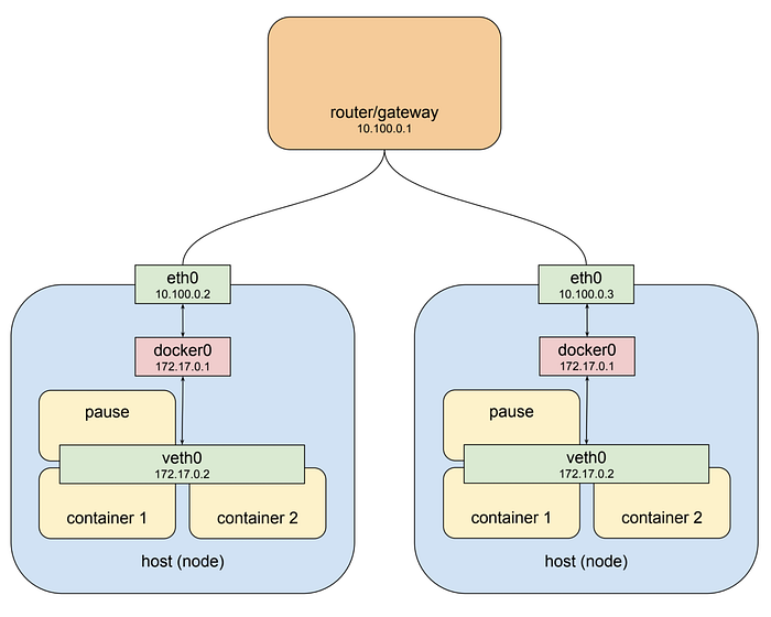
The host on the left has interface eth0 with an address of 10.100.0.2, whose default gateway is the router at 10.100.0.1. Connected to that interface is bridge docker0 with an address of 172.17.0.1, and connected to that is interface veth0 with address 172.17.0.2. The veth0 interface was created with the pause container and is visible inside all three containers by virtue of the shared network stack. Because of local routing rules set up when the bridge was created any packet arriving at eth0 with a destination address of 172.17.0.2 will be forwarded to the bridge, which will then send it on to veth0. Sounds ok so far. If we know we have a pod at 172.17.0.2 on this host we can add rules to our router setting the next hop for that address to 10.100.0.2 and they will get forwarded from there to veth0. Dandy! Now let’s look at the other host.
The host on the right also has eth0, with an address of 10.100.0.3, using the same default gateway at 10.100.0.1, and again connected to it is the docker0 bridge with an address of 172.17.0.1. Hmm. That’s going to be an issue. Now this address might not actually be the same as the other bridge on host 1. I’ve made it the same here because that’s a pathological worst case, and it might very well work out that way if you just installed docker and let it do its thing. But even if the chosen network is different this highlights the more fundamental problem which is that one node typically has no idea what private address space was assigned to a bridge on another node, and we need to know that if we’re going to send packets to it and have them arrive at the right place. Clearly some structure is required.
Kubernetes provides that structure in two ways. First, it assigns an overall address space for the bridges on each node, and then assigns the bridges addresses within that space, based on the node the bridge is built on. Secondly it adds routing rules to the gateway at 10.100.0.1 telling it how packets destined for each bridge should be routed, i.e. which node’s eth0 the bridge can be reached through. Such a combination of virtual network interfaces, bridges, and routing rules is usually called an overlay network. When talking about kubernetes I usually call this network the “pod network” because it is an overlay network that allows pods to communicate back and forth on any node. Here is the drawing above with kubernetes in play:
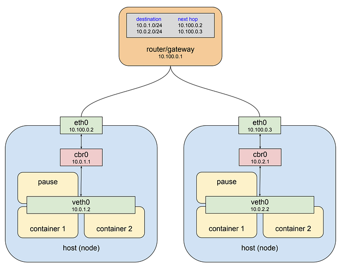
One thing that should jump out is that I’ve changed the name of the bridges from “docker0” to “cbr0.” Kubernetes does not use the standard docker bridge device and in fact “cbr” is short for “custom bridge.” I don’t know everything that is custom about it, but it is one of the important differences between docker running on kubernetes vs. a default installation. Another thing to note is that the address space assigned to the bridges in this example is 10.0.0.0/14. That’s taken from one of our staging clusters in Google Cloud and so is a real-world example. Your cluster may be assigned an entirely different range. Unfortunately there is no way to expose this using the kubectl utility at the moment, but on GCP you can run gcloud container clusters describe <cluster> command and look for the clusterIpv4Cidr property.
Generally you won’t need to think about how this network functions. When a pod talks with another pod it most often does so through the abstraction of a service, a kind of software-defined proxy that will be the subject of the next post in this series. But pod network addresses will pop up in logs and when debugging and in some scenarios you may need to explicitly route this network. For example traffic leaving a kubernetes pod bound for any address in the 10.0.0.0/8 range is not NAT’d by default, so if you communicate with services on another private network in that range you may need to set up rules to route the packets back to the pods. Hopefully this article will help you take the right steps to make such scenarios work correctly.
Understanding Kubernetes Networking: Services
In the first post I showed a hypothetical cluster with two server pods and described how they are able to communicate across nodes. Here I want to build on that example to describe how a Kubernetes service enables load balancing across a set of server pods, allowing client pods to operate independently and durably. To create server pods we can use a deployment such as this:
kind: Deployment
apiVersion: extensions/v1beta1
metadata:
  name: service-test
spec:
  replicas: 2
  selector:
    matchLabels:
      app: service_test_pod
  template:
    metadata:
      labels:
        app: service_test_pod
    spec:
      containers:
      - name: simple-http
        image: python:2.7
        imagePullPolicy: IfNotPresent
        command: ["/bin/bash"]
        args: ["-c", "echo \"<p>Hello from $(hostname)</p>\" > index.html; python -m SimpleHTTPServer 8080"]
        ports:
        - name: http
          containerPort: 8080
This deployment creates two very simple http server pods that respond on port 8080 with the hostname of the pod they are running in. After creating this deployment using kubectl apply we can see that the pods are running in the cluster, and we can also query to see what their pod network addresses are:
$ kubectl apply -f test-deployment.yaml
 deployment "service-test" created$ kubectl get pods
 service-test-6ffd9ddbbf-kf4j2   1/1   Running   0   15s
 service-test-6ffd9ddbbf-qs2j6   1/1   Running   0   15s$ kubectl get pods --selector=app=service_test_pod -o jsonpath='{.items[*].status.podIP}'
 10.0.1.2 10.0.2.2
We can demonstrate that the pod network is operating by creating a simple client pod to make a request, and then viewing the output.
apiVersion: v1
kind: Pod
metadata:
  name: service-test-client1
spec:
  restartPolicy: Never
  containers:
  - name: test-client1
    image: alpine
    command: ["/bin/sh"]
    args: ["-c", "echo 'GET / HTTP/1.1\r\n\r\n' | nc 10.0.2.2 8080"]
After this pod is created the command will run to completion, the pod will enter the “completed” state and the output can then be retrieved with kubectl logs:
$ kubectl logs service-test-client1
HTTP/1.0 200 OK
<!-- blah -->
<p>Hello from service-test-6ffd9ddbbf-kf4j2</p>
Nothing in this example shows which node the client pod was created on, but regardless of where it ran in the cluster it would be able to reach the server pod and get a response back thanks to the pod network. However if the server pod were to die and be restarted, or be rescheduled to a different node, its IP would almost certainly change and the client would break. We avoid this by creating a service.
kind: Service
apiVersion: v1
metadata:
  name: service-test
spec:
  selector:
    app: service_test_pod
  ports:
  - port: 80
    targetPort: http
A service is a type of kubernetes resource that causes a proxy to be configured to forward requests to a set of pods. The set of pods that will receive traffic is determined by the selector, which matches labels assigned to the pods when they were created. Once the service is created we can see that it has been assigned an IP address and will accept requests on port 80.
$ kubectl get service service-test
NAME           CLUSTER-IP     EXTERNAL-IP   PORT(S)   AGE
service-test   10.3.241.152   <none>        80/TCP    11s
Requests can be sent to the service IP directly but it would be better to use a hostname that resolves to the IP address. Fortunately kubernetes provides an internal cluster DNS that resolves the service name, and with a slight change to the client pod we can make use of it:
apiVersion: v1
kind: Pod
metadata:
  name: service-test-client2
spec:
  restartPolicy: Never
  containers:
  - name: test-client2
    image: alpine
    command: ["/bin/sh"]
    args: ["-c", "echo 'GET / HTTP/1.1\r\n\r\n' | nc service-test 80"]
After this pod runs to completion the output shows that the service forwarded the request to one of the server pods.
$ kubectl logs service-test-client2
HTTP/1.0 200 OK
<!-- blah -->
<p>Hello from service-test-6ffd9ddbbf-kf4j2</p>
You can continue to run the client pod and you’ll see responses from both server pods with each getting approximately 50% of the requests. If your goal is to understand how this actually works then a good place to start is with that IP address that our service was assigned.
The service network
The IP that the test service was assigned represents an address on a network, and you might have noted that the network is not the same as the one the pods are on.
thing        IP               network
-----        --               -------
pod1         10.0.1.2         10.0.0.0/14
pod2         10.0.2.2         10.0.0.0/14
service      10.3.241.152     10.3.240.0/20
It’s also not the same as the private network the nodes are on, which will become clearer below. In the first post I noted that the pod network address range is not exposed via kubectl and so you need to use a provider-specific command to retrieve this cluster property. The same is true of the service network address range. If you’re running in Google Container Engine you can do this:
$ gcloud container clusters describe test | grep servicesIpv4Cidr
servicesIpv4Cidr: 10.3.240.0/20
The network specified by this address space is called the “service network.” Every service that is of type “ClusterIP” will be assigned an IP address on this network. There are other types of services, and I’ll talk about a couple of them in the next post on ingress, but ClusterIP is the default and it means “the service will be assigned an IP address reachable from any pod in the cluster.” You can see the type of a service by running the kubectl describe services command with the service name.
$ kubectl describe services service-test
Name:                   service-test
Namespace:              default
Labels:                 <none>
Selector:               app=service_test_pod
Type:                   ClusterIP
IP:                     10.3.241.152
Port:                   http    80/TCP
Endpoints:              10.0.1.2:8080,10.0.2.2:8080
Session Affinity:       None
Events:                 <none>
Like the pod network the service network is virtual, but it differs from the pod network in some interesting ways. Consider the pod network address range 10.0.0.0/14. If you go looking on the hosts that make up the nodes in your cluster, listing bridges and interfaces you’re going to see actual devices configured with addresses on this network. Those are the virtual ethernet interfaces for each pod and the bridges that connect them to each other and the outside world.
Now look at the service network 10.3.240.0/20. You can ifconfig to your heart’s delight and you will not find any devices configured with addresses on this network. You can examine the routing rules at the gateway that connects all the nodes and you won’t find any routes for this network. The service network does not exist, at least not as connected interfaces. And yet as we saw above when we issued a request to an IP on this network somehow that request made it to our server pod running on the pod network. How did that happen? Let’s follow a packet and see.
Imagine that the commands we ran above created the following pods in a test cluster:

Here we have two nodes, the gateway connecting them (that also has the routing rules for the pod network), and three pods: the client pod on node 1, a server pod also on node 1, and another server pod on node 2. The client makes an http request to the service using the DNS name service-test. The cluster DNS system resolves that name to the service cluster IP 10.3.241.152, and the client pod ends up creating an http request that results in some packets being sent with that IP in the destination field.
IP networks are typically configured with routes such that when an interface cannot deliver a packet to its destination because no device with that specified address exists locally it forwards the packet on to its upstream gateway. So the first interface that sees the packets in this example is the virtual ethernet interface inside the client pod. That interface is on the pod network 10.0.0.0/14 and doesn’t know any devices with address 10.3.241.152, so it forwards the packet to its gateway which is the bridge cbr0. Bridges are pretty dumb and just pass traffic back and forth so the bridge sends the packet on to the host/node ethernet interface.
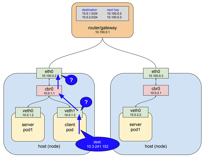
The host/node ethernet interface in this example is on the network 10.100.0.0/24 and it doesn’t know any devices with the address 10.3.241.152 either, so again what would normally happen is the packet would be forwarded out to this interface’s gateway, the top level router shown in the drawing. Instead what actually happens is that the packet is snagged in flight and redirected to one of the live server pods.

When I first started working with kubernetes three years ago what was happening in the diagram above seemed pretty magical. Somehow my clients were able to connect to an address with no interface associated with it and those packets popped out at the right place in the cluster. As I later learned the answer to this mystery is a piece of software called kube-proxy.
kube-proxy
Like everything in kubernetes a service is just a resource, a record in a central database, that describes how to configure some bit of software to do something. In fact a service affects the configuration and behavior of several components in the cluster, but the one that’s important here, the one that makes the magic described above happen, is kube-proxy. Many of you will have a general idea of what this component does based on the name, but there are some things about kube-proxy that make it quite different from a typical reverse-proxy like haproxy or linkerd.
The general behavior of a proxy is to pass traffic between clients and servers over two open connections. Clients connect inbound to a service port, and the proxy connects outbound to a server. Since all proxies of this kind run in user space this means that packets are marshaled into user space and back to kernel space on every trip through the proxy. Initially kube-proxy was implemented as just such a user-space proxy, but with a twist. A proxy needs an interface, both to listen on for client connections, and to use to connect to back-end servers. The only interfaces available on a node are either a) the host’s ethernet interface; or b) the virtual ethernet interfaces on the pod network.
Why not use an address on one of those networks? I don’t have any inside knowledge but I imagine that it became clear pretty early in the project that doing so would have complicated the routing rules for those networks, which are designed to serve the needs of pods and nodes, both of which are ephemeral entities in the cluster. Services clearly needed their own, stable, non-conflicting network address space, and a system of virtual IPs makes the most sense. However, as we noted there are no actual devices on this network. You can make use of a pretend network in routing rules, firewall filters, etc., but you can’t actually listen on a port or open a connection through an interface that doesn’t exist.
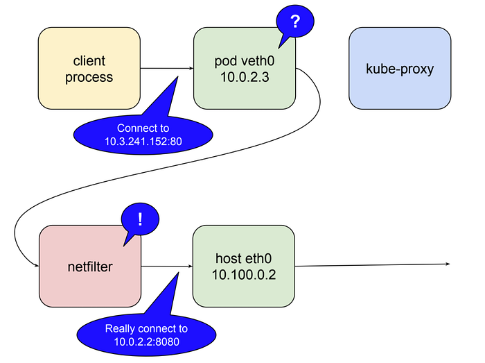
Kubernetes gets around this using a feature of the linux kernel called netfilter, and a user space interface to it called iptables. There’s not enough room in this already-long post to go into exactly how this works. If you want to read more about it the netfilter page is a good place to start. Here’s the tl;dr: netfilter is a rules-based packet processing engine. It runs in kernel space and gets a look at every packet at various points in its life cycle. It matches packets against rules and when it finds a rule that matches it takes the specified action. Among the many actions it can take is redirecting the packet to another destination. That’s right, netfilter is a kernel space proxy. The following illustrates the role netfilter plays when kube-proxy is running as a user space proxy.

In this mode kube-proxy opens a port (10400 in the example above) on the local host interface to listen for requests to the test-service, inserts netfilter rules to reroute packets destined for the service IP to its own port, and forwards those requests to a pod on port 8080. That is how a request to 10.3.241.152:80 magically becomes a request to 10.0.2.2:8080. Given the capabilities of netfilter all that’s required to make this all work for any service is for kube-proxy to open a port and insert the correct netfilter rules for that service, which it does in response to notifications from the master api server of changes in the cluster.
There’s one more little twist to the tale. I mentioned above that user space proxying is expensive due to marshaling packets. In kubernetes 1.2 kube-proxy gained the ability to run in iptables mode. In this mode kube-proxy mostly ceases to be a proxy for inter-cluster connections, and instead delegates to netfilter the work of detecting packets bound for service IPs and redirecting them to pods, all of which happens in kernel space. In this mode kube-proxy’s job is more or less limited to keeping netfilter rules in sync.
To wrap up let’s compare everything described above to the requirements set out for a reliable proxy at the beginning of the post. Is the services proxy system durable? By default kube-proxy runs as a systemd unit, so it will be restarted if it fails. In Google Container Engine it runs as a pod controlled by a daemonset. This will be the future default, possibly with version 1.9. As a user space proxy kube-proxy still represents a single point of connection failure. When running in iptables mode the system is highly durable from the perspective of local pods attempting connections, since if the node is up so is netfilter.
Is the service proxy aware of healthy server pods that can handle requests? As mentioned above kube-proxy listens to the master api server for changes in the cluster, which includes changes to services and endpoints. As it receives updates it uses iptables to keep the netfilter rules in sync. When a new service is created and its endpoints are populated kube-proxy gets the notification and creates the necessary rules. Similarly it removes rules when services are deleted. Health checks against endpoints are performed by the kubelet, another component that runs on every node, and when unhealthy endpoints are found kubelet notifies kube-proxy via the api server and netfilter rules are edited to remove this endpoint until it becomes healthy again.
All of this adds up to a highly-available cluster-wide facility for proxying requests between pods while allowing pods themselves to come and go as the needs of the cluster change. The system is not without its downsides, however. The most basic one is that it only works as described for requests that originate inside the cluster, i.e. requests from one pod to another. Another is a consequence of the way the netfilter rules work: for requests arriving from outside the cluster the rules obfuscate the origin IP. This has been a source of some debate and solutions are under active consideration. I’ll look more closely at both of these issues when we discuss ingress in the final post of this series.
Understanding Kubernetes Networking: Ingress
First, having just returned from kubecon 2017 in Austin I’m reminded of something I might have made clear earlier in the series. Kubernetes is a rapidly maturing platform. Much of the architecture is plug-able, and this includes networking. What I have been describing here is the default implementation on Google Kubernetes Engine. I haven’t seen Amazon’s Elastic Kubernetes Service yet but I think it will be close to the default implementation there as well. To the extent that kubernetes has a “standard” way of handling networking I think these posts describe it in its fundamental aspects. You have to start somewhere, and getting these concepts well in hand will help when you start to think about alternatives like unified service meshes, etc. With that said, let’s talk ingress.

Routing is not load balancing
In the last post we created a deployment with a couple of pods, and a service that was assigned an IP, called the “cluster IP” to which requests intended for the pods were sent. I’ll continue building from that example here. Recall that the service’s cluster IP 10.3.241.152 is in an IP address range that is separate from the pod network, and from the network that the nodes themselves are on. I called this address space the “services network”, although it barely deserves the name, having no connected devices on it and consisting as it does entirely of routing rules. In the example we showed how this network is implemented by a kubernetes component called kube-proxy collaborating with a linux kernel module called netfilter to trap and reroute traffic sent to the cluster IP so that it is sent to a healthy pod instead.

Up to now we’ve been talking about “connections” and “requests” and even the more ambiguous “traffic,” but to understand why kubernetes ingress works the way it does we need to get more specific. Connections and requests operate at OSI layer 4 (tcp) or layer 7 (http, rpc, etc). Netfilter rules are routing rules, and they operate on IP packets at layer 3. All routers, including netfilter, make routing decisions based more or less solely on information contained in the packet; generally where it is from and where it is going. So to describe this behavior in layer 3 terms: each packet destined for the service at10.3.241.152:80 that arrives at a node’s eth0 interface is processed by netfilter, matches the rules established for our service, and is forwarded to the IP of a healthy pod.
It seems pretty clear that any mechanism we use to allow external clients to call into our pods has to make use of this same routing infrastructure. That is, those external clients have to end up calling the cluster IP and port, because that is the “front end” for all the machinery we’ve talked about up to this point that makes it possible for us not to care where a pod is running at any given time. It’s not immediately obvious how to make this happen, however. The cluster IP of a service is only reachable from a node’s ethernet interface. Nothing outside the cluster knows what to do with addresses in that range. How can we forward traffic from a publicly visible IP endpoint to an IP that is only reachable once the packet is already on a node?
If you were trying to come up with a solution to this problem one of the things you might do is examine the netfilter rules using the iptables utility, and if you did you would discover something that seems surprising at first: the rules for the example service are not scoped to a particular origin network. That is, any packet from anywhere that arrives on the node’s ethernet interface with a destination of 10.3.241.152:80 is going to match and get routed to a pod. So can we just give clients that cluster IP, maybe assign it a friendly domain name, and then add a route to get those packets to one of the nodes?

If you set things up that way it will work. Clients call the cluster IP, the packets follow a route down to a node, and get forwarded to a pod. At this point you might be tempted to put a bow on it, but this solution suffers from some serious problems. The first is simply that nodes are ephemeral, just like pods. They are not as ephemeral as pods, but they can be migrated to a new vm, clusters can scale up and down, etc. Routers operating on layer 3 packets don’t know healthy services from unhealthy. They expect the next hop in the route to be stable and available. If the node becomes unreachable the route will break and stay broken for a significant time in most cases. Even if the route were durable you’d have all your external traffic passing through a single node, which is probably not optimal.
However we bring client traffic in we have to do so in a way that doesn’t depend on the health of any single node in the cluster. There’s really no reliable way to do this using routing without some active management of the router, which is exactly kube-proxy’s role in managing netfilter. Extending kubernetes responsibilities out to management of an external router probably didn’t make much sense to the designers, especially given that we already have proven tools for distributing client traffic to a set of machines. They’re called load balancers, and not surprisingly that is the solution for kubernetes ingress that actually works durably. To see exactly how its time to climb up out of the layer 3 basement and talk about connections again.
To use a load balancer for distributing client traffic to the nodes in a cluster we need a public IP the clients can connect to, and we need addresses on the nodes themselves to which the load balancer can forward the requests. For the reasons discussed above we can’t easily create a stable static route between the gateway router and the nodes using the service network (cluster IP). The only other addresses available are on the network the nodes’ ethernet interfaces are connected to, 10.100.0.0/24 in the example. The gateway router already knows how to get packets to these interfaces, and connections sent from the load balancer to the router will get to the right place. But if a client wants to connect to our service on port 80 we can’t just send packets to that port on the nodes’ interfaces.

The reason why this fails is readily apparent. There is no process listening on 10.100.0.3:80 (or if there is it’s the wrong one), and the netfilter rules that we were hoping would intercept our request and direct it to a pod don’t match that destination address. They only match the cluster IP on the service network at 10.3.241.152:80. So those packets can’t be delivered when they arrive on that interface and the kernel responds with ECONNREFUSED. That leaves us with a conundrum: the network that netfilter is set up to forward packets for is not easily routable from the gateway to the nodes, and the network that is easily routable is not the one netfilter is forwarding for. The way to solve this problem is to create a bridge between these networks, and that is exactly what kubernetes does with something called a NodePort.
NodePort Services
The example service that we created in the last post did not specify a type, and so took the default type ClusterIP. There are two other types of service that add additional capabilities, and the one that is important next is type NodePort. Here’s the example service as a NodePort service.
kind: Service
apiVersion: v1
metadata:
  name: service-test
spec:
  type: NodePort
  selector:
    app: service_test_pod
  ports:
  - port: 80
    targetPort: http
A service of type NodePort is a ClusterIP service with an additional capability: it is reachable at the IP address of the node as well as at the assigned cluster IP on the services network. The way this is accomplished is pretty straightforward: when kubernetes creates a NodePort service kube-proxy allocates a port in the range 30000–32767 and opens this port on the eth0 interface of every node (thus the name “NodePort”). Connections to this port are forwarded to the service’s cluster IP. If we create the service above and run kubectl get svc service-test we can see the NodePort that has been allocated for it.
$ kubectl get svc service-test
NAME           CLUSTER-IP     EXTERNAL-IP   PORT(S)           AGE
service-test   10.3.241.152   <none>        80:32213/TCP      1m
In this case our service was allocated the NodePort 32213. This means that we can now connect to the service on either node in the example cluster, at 10.100.0.2:32213 or 10.100.0.3:32213 and traffic will get forwarded to the service. With this piece in place we now have a complete pipeline for load balancing external client requests to all the nodes in the cluster.

In the diagram above the client connects to the load balancer via a public IP address, the load balancer selects a node and connects to it at 10.100.0.3:32213, kube-proxy receives this connection and forwards it to the service at the cluster IP 10.3.241.152:80, at which point the request matches the netfilter rules and gets redirected to the server pod on 10.0.2.2:8080. It might all seem a little complicated, and it is in some ways, but it’s hard to think of a more straightforward solution that maintains all the cool capabilities put in place by the pod and service networks.
This mechanism is not without its issues. The use of NodePorts exposes your service to clients on a non-standard port. This is often not a problem as the load balancer can expose the usual port and mask the NodePort from end users. But in some scenarios such as internal load balancing on Google Cloud you’re going to be forced to propagate the NodePort upstream. NodePorts are also a limited resource, although 2768 is probably enough for even the largest clusters. For most applications you can let kubernetes choose the ports randomly, but if needed you can also set them explicitly. Lastly there are some restrictions around the preservation of source IPs in requests. You can refer to the documentation article on the topic for information on how to manage these issues.
NodePorts are the fundamental mechanism by which all external traffic gets into a kubernetes cluster. However by themselves they are not a complete solution. For the reasons outlined above you’re always going to need a load balancer of some kind in front of the cluster, whether your clients are internal or coming in over the public network. The platform’s designers recognized this and provided two different ways to specify load balancer configuration from within kubernetes itself, so let’s take a quick look at that next.
LoadBalancer Services and Ingress Resources
These last two concepts are among the more complex functions that kubernetes performs, but I’m not going to spend a lot of time on them because they don’t really change any of what we just talked about. All external traffic ends up entering the cluster through a NodePort as described above. The designers could have stopped there and just let you worry about public IPs and load balancers, and indeed in certain situations such as running on bare metal or in your home lab that’s what you’re going to have to do. But in environments that support API-driven configuration of networking resources kubernetes makes it possible to define everything in one place.
The first and simplest approach to this is a third type of kubernetes service called a LoadBalancer service. A service of type LoadBalancer has all the capabilities of a NodePort service plus the ability to build out a complete ingress path, assuming you are running in an environment like GCP or AWS that supports API-driven configuration of networking resources.
kind: Service
apiVersion: v1
metadata:
  name: service-test
spec:
  type: LoadBalancer
  selector:
    app: service_test_pod
  ports:
  - port: 80
    targetPort: http
If we delete and recreate the example service on Google Kubernetes Engine we can soon see with kubectl get svc service-test that an external IP has been allocated.
$ kubectl get svc service-test
NAME      CLUSTER-IP      EXTERNAL-IP     PORT(S)          AGE
openvpn   10.3.241.52     35.184.97.156   80:32213/TCP     5m
I say “soon” although allocation of the external IP can take several minutes to happen, which is not surprising given the number of resources that have to be brought up. On GCP, for example, this requires the system to create an external IP, a forwarding rule, a target proxy, a backend service, and possibly an instance group. Once the IP has been allocated you can connect to your service through it, assign it a domain name and distribute it to clients. As long as the service isn’t destroyed and recreated (and there are rarely good reasons to do that) the IP won’t change.
Services of type LoadBalancer have some limitations. You cannot configure the lb to terminate https traffic. You can’t do virtual hosts or path-based routing, so you can’t use a single load balancer to proxy to multiple services in any practically useful way. These limitations led to the addition in version 1.2 of a separate kubernetes resource for configuring load balancers, called an Ingress. LoadBalancer services are all about extending a single service to support external clients. By contrast an Ingress is a separate resource that configures a load balancer much more flexibly. The Ingress API supports TLS termination, virtual hosts, and path-based routing. It can easily set up a load balancer to handle multiple backend services.
The Ingress API is too large a topic to go into in much detail here, since as mentioned it has little to do with how ingress actually works at the network level. The implementation follows a basic kubernetes pattern: a resource type and a controller to manage that type. The resource in this case is an Ingress, which comprises a request for networking resources. Here’s what an Ingress resource might look like for our test service.
apiVersion: extensions/v1beta1
kind: Ingress
metadata:
  name: test-ingress
  annotations:
    kubernetes.io/ingress.class: "gce"
spec:
  tls:
    - secretName: my-ssl-secret
  rules:
  - host: testhost.com
    http:
      paths:
      - path: /*
        backend:
          serviceName: service-test
          servicePort: 80
The ingress controller is responsible for satisfying this request by driving resources in the environment to the necessary state. When using an Ingress you create your services as type NodePort and let the ingress controller figure out how to get traffic to the nodes. There are ingress controller implementations for GCE load balancers, AWS elastic load balancers, and for popular proxies such as nginx and haproxy. Note that mixing Ingress resources with LoadBalancer services can cause subtle issues in some environments. These can all be easily worked around, but in general its probably best just to use Ingress for even simple services.
HostPort and HostNetwork
The last two things I want to talk about really fall more into the category of interesting curiosities rather than useful tools. In fact I would suggest that they are anti-patterns for 99.99 per cent of use cases, and any implementation that makes use of either should get an automatic design review. I considered leaving them out entirely, but they are paths of ingress of a sort and so it’s worth a very brief look at what they do.
The first of these is HostPort. This is a property of a container (declared in a ContainerPort structure), and when set to a given integer port number causes that port to be opened on the node and forwarded directly to the container. There is no proxying, and the port is only opened on nodes the container is running on. In the early days of the platform before the addition of DaemonSets and StatefulSets this was a trick that could be used to make sure only one container of a type ran on any given node. For example I once used it to implement an elasticsearch cluster by setting HostPort to 9200 and specifying the same number of replicas as there were nodes. This would be considered a horrible hack now, and unless you are implementing a kubernetes system component you’re very unlikely to ever want HostPort set.
The second of these is even weirder in the context of kubernetes, and that is the HostNetwork property of a pod. When set to true this has the same effect as the --network=host argument to docker run. It causes all the containers in the pod to use the node’s network namespace, i.e. they all have access to eth0 and open ports directly on this interface. I don’t think it’s a stretch to suggest that you are never, ever going to need to do this. If you have a use case for this then you’re very likely already a kubernetes contributor and don’t require any assistance from me.
Wrap-up
And that wraps up this three-part series on kubernetes networking. I’ve enjoyed learning about and working with this platform, and I hope some of that enthusiasm comes through in these articles. I think kubernetes heralds a revolution in terms of making it possible for us to reliably manage and interconnect fleets of containers rather than fleets of servers. It many ways it really is a data center in a bottle, and so it isn’t surprising that there is a fair bit of underlying complexity. I wrote these posts because I think that once you learn how each of the pieces works it all makes sense in a pretty elegant way. Hopefully I’ve contributed to making the path of entry easier for future new users of the platform.
Thanks for reading ❤
If you liked this post, share it with all of your programming buddies!
Follow me on Facebook | Twitter
Further reading about Kubernetes
☞ Docker and Kubernetes: The Complete Guide
☞ Learn DevOps: The Complete Kubernetes Course
☞ Docker and Kubernetes: The Complete Guide
☞ Kubernetes Certification Course with Practice Tests
☞ An illustrated guide to Kubernetes Networking
☞ An Introduction to Kubernetes: Pods, Nodes, Containers, and Clusters
☞ An Introduction to the Kubernetes DNS Service
☞ Kubernetes Deployment Tutorial For Beginners
☞ Kubernetes Tutorial - Step by Step Introduction to Basic Concepts
#kubernetes #docker #devops