Combining 3 Arduino boards to create a GPS tracker & data logger.
I had an idea to combine the new Arduino Nano 33 BLE Sense with an SD card and GPS module for a side project that logs GPS and IMU data.
I decided to purchase the Nano 33, the MKR Mem Shield, and the MKR GPS Shield and connect them all together. Unbeknownst to me at the time, these boards aren’t footprint-compatible, so I combined them with a breadboard 😐.
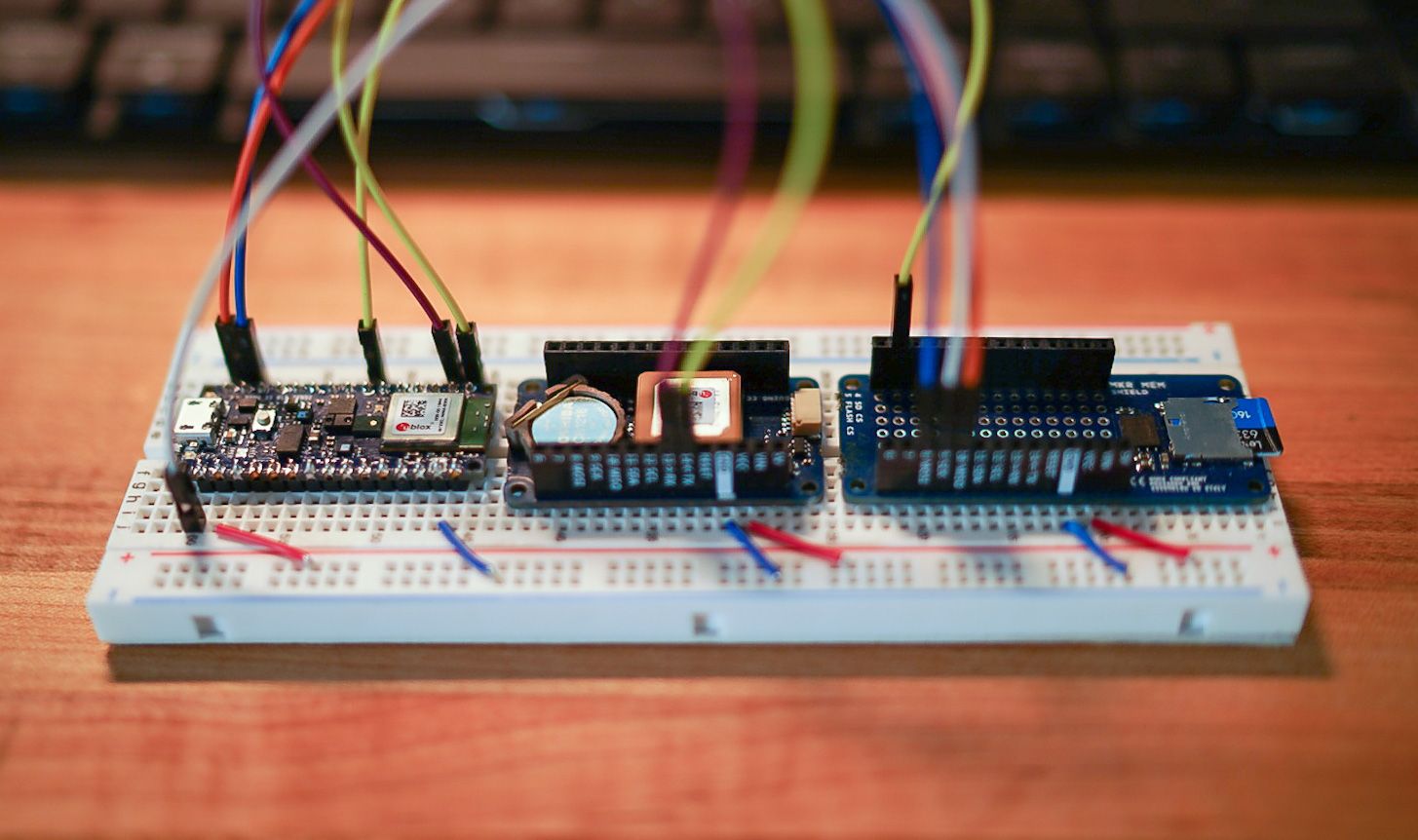
It took a little while to get all the libraries installed and everything connected appropriately. The biggest challenge was the GPS module. It really helps to start debugging the GPS’ example code outside; where satellite signal is available 😉.
Prototype Code
The full Arduino sketch for the above connected system is here. But, might as well have a quick overview of the code. Throwing the imports and definitions below:
#include <SparkFun_Ublox_Arduino_Library.h>
#include <Arduino_LSM9DS1.h>
#include <Arduino_APDS9960.h>
#include <SPI.h>
#include <SD.h>

// SD Vars
File dataFile;
int chipSelect = 4;

// GPS Vars
SFE_UBLOX_GPS myGPS; // Connected via UART
long latitude = 0;
long longitude = 0;
long speed = 0;
byte satellites = 0;
int timeout = 50;
long lastGPSTime = 0;

// IMU Vars
float ax, ay, az;
float gx, gy, gz;

// Misc
bool DEBUG = true;
int counter = 0;

#define LEDR        (22u)
#define LEDG        (23u)
#define LEDB        (24u)
Next, we need to do all the GPS and SD card setup. The tricky part here was making sure to remove the DATALOG.csv file every time we start up.
void setup()
{
  // Setup User Terminal
  Serial.begin(115200); // UART to PC/Mac
  while(!Serial);
  Serial1.begin(9600);  // UART to GPS
  while(!Serial1);

  // Initialize digital pin LED_BUILTIN as an output.
  pinMode(LED_BUILTIN, OUTPUT);
  pinMode(LEDR, OUTPUT);
  pinMode(LEDB, OUTPUT);
  pinMode(LEDG, OUTPUT);

  digitalWrite(LEDR, HIGH); // LOW triggered LED....
  digitalWrite(LEDG, HIGH);
  digitalWrite(LEDB, HIGH);

  // Setup GPS
  if (!myGPS.begin(Serial1)) {
    Serial.println(F("GPS not detected!"));
    while (1);
  }
  Serial.println("GPS Started!");

  // Setup SD Card
  if (!SD.begin(chipSelect)) {
    Serial.println("SD Card failed or not present!");
    while (1);
  }

  // Remove Existing DATALOG.CSV file
  if(SD.exists("DATALOG.CSV")) {
    SD.remove("DATALOG.CSV");
    dataFile = SD.open("DATALOG.CSV", FILE_WRITE);
    dataFile.close();
  }

  delay(500); // Make sure existing DATALOG.CSV file is gone

  // Create new CSV file with appropriate headers
  dataFile = SD.open("DATALOG.CSV", FILE_WRITE);
  dataFile.println("Count,AccX,AccY,AccZ,GyrX,GyrY,GyrZ,Lat,Long,Speed");

  // Done with SD Card Init
  Serial.println("SD Card Initialized!");

  // Setup Gesture Sensor
  if (!APDS.begin()) {
    Serial.println("Error initializing gesture sensor!");
  }
  APDS.setGestureSensitivity(85);
  Serial.println("Gesture sensor initialized!");

  // Setup IMU
  if (!IMU.begin()) {
    Serial.println("Failed to initialize IMU!");
    while(1);
  }
  Serial.println("IMU initialized!");
}
Now we can log all of the data to the SD Card. Note that we could use the Gesture sensor to stop and start recording (in the main loop).
void loop()
{
  if (millis() - lastGPSTime > 500) {
    lastGPSTime = millis(); // Update the timer

    latitude = myGPS.getLatitude(timeout);
    longitude = myGPS.getLongitude(timeout);
    speed = myGPS.getGroundSpeed(timeout);
    satellites = myGPS.getSIV(timeout);

    if(DEBUG) {
      Serial.print(F("Lat: "));
      Serial.print(latitude);
      Serial.print(F(" Long: "));
      Serial.print(longitude);
      Serial.print(F(" (degrees * 10^-7)"));
      Serial.print(F(" Speed: "));
      Serial.print(speed);
      Serial.print(F(" (mm/s)"));
      Serial.print(F(" satellites: "));
      Serial.println(satellites);
    }
  }

  if (IMU.accelerationAvailable()) {
    IMU.readAcceleration(ax, ay, az);
    if(DEBUG) {
      Serial.print(F("Accel x: "));
      Serial.print(ax);
      Serial.print(F(" y: "));
      Serial.print(ay);
      Serial.print(F(" z: "));
      Serial.println(az);
    }
  }

  if (IMU.gyroscopeAvailable()) {
    IMU.readGyroscope(gx, gy, gz);
    if(DEBUG) {
      Serial.print(F("Gyro x: "));
      Serial.print(gx);
      Serial.print(F(" y: "));
      Serial.print(gy);
      Serial.print(F(" z: "));
      Serial.println(gz);
    }
  }

  if (APDS.gestureAvailable()) {
    // A gesture was detected, read and print to serial monitor
    switch (APDS.readGesture()) {
      case GESTURE_UP:
        Serial.println("Detected UP gesture");
        break;
      case GESTURE_DOWN:
        Serial.println("Detected DOWN gesture");
        break;
      case GESTURE_LEFT:
        Serial.println("Detected LEFT gesture");
        break;
      case GESTURE_RIGHT:
        Serial.println("Detected RIGHT gesture");
        break;
      default:
        // ignore
        break;
    }
  }

  if (dataFile) {
    counter += 1;
    String dataString = "";
    dataString += String(counter) + ",";
    dataString += String(ax) + ",";
    dataString += String(ay) + ",";
    dataString += String(az) + ",";
    dataString += String(gx) + ",";
    dataString += String(gy) + ",";
    dataString += String(gz) + ",";
    dataString += String(latitude) + ",";
    dataString += String(longitude) + ",";
    dataString += String(speed);
    dataFile.println(dataString);
  }

  delay(150); // Don't pound too hard
}
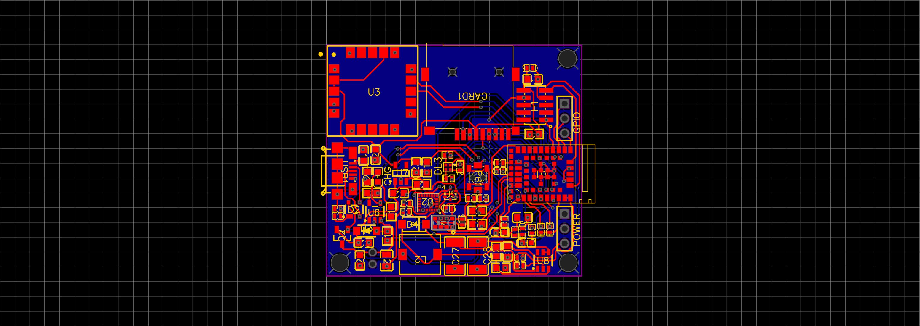
So this is all fine and good. Prototype concept has been vetted! Time to build a custom PCB with the same functionality.
#iot #arduino #imu #bluetooth #sensor #hardware #firmware #gps