This is part one of a two-part series. In this part, I will tell you how you can control any device using your smartphone or voice commands from either Google Assistant or Alexa. The next part will be about how to use gestures to control any of your home appliances using Computer Vision and Raspberry Pi.
Why would you want to automate?
- Saves time
- Much more efficient
- Ability to control any device from anywhere in the world
- Insanely useful for lazy chaps like me
Things you will need
- ESP8266-Node MCU (Microcontroller) ($2 in aliexpress)
- Breadboard power supply or any other 5V source ($0.71 in aliexpress)
- Relay board — 2 channel, 4 channel, 8 channel according to your needs ($1 in aliexpress)
- Jumper Wires — Female to Female (under $1 in aliexpress)
I will explain the use of each of these items below:
Taking a Look at the Required Components
Relay board
Relay board
The Relay board uses electromagnets to make and break the circuits. This one here has 4 channels, but you can easily buy up to 16 channels. The number of channels relates to the number of devices that you can connect at once. This relay can handle up to 10A 250V AC. There are 4 input pins (IN 1–4) to control 4 relays. You can use Node-MCU to power the board, but it is a good idea to isolate the board from the micro-controller, to do that connect voltage pin from Node-MCU to VCC and separate 5V power supply to JD-VCC and GND.
This is where the breadboard power supply comes in.
Breadboard power supply
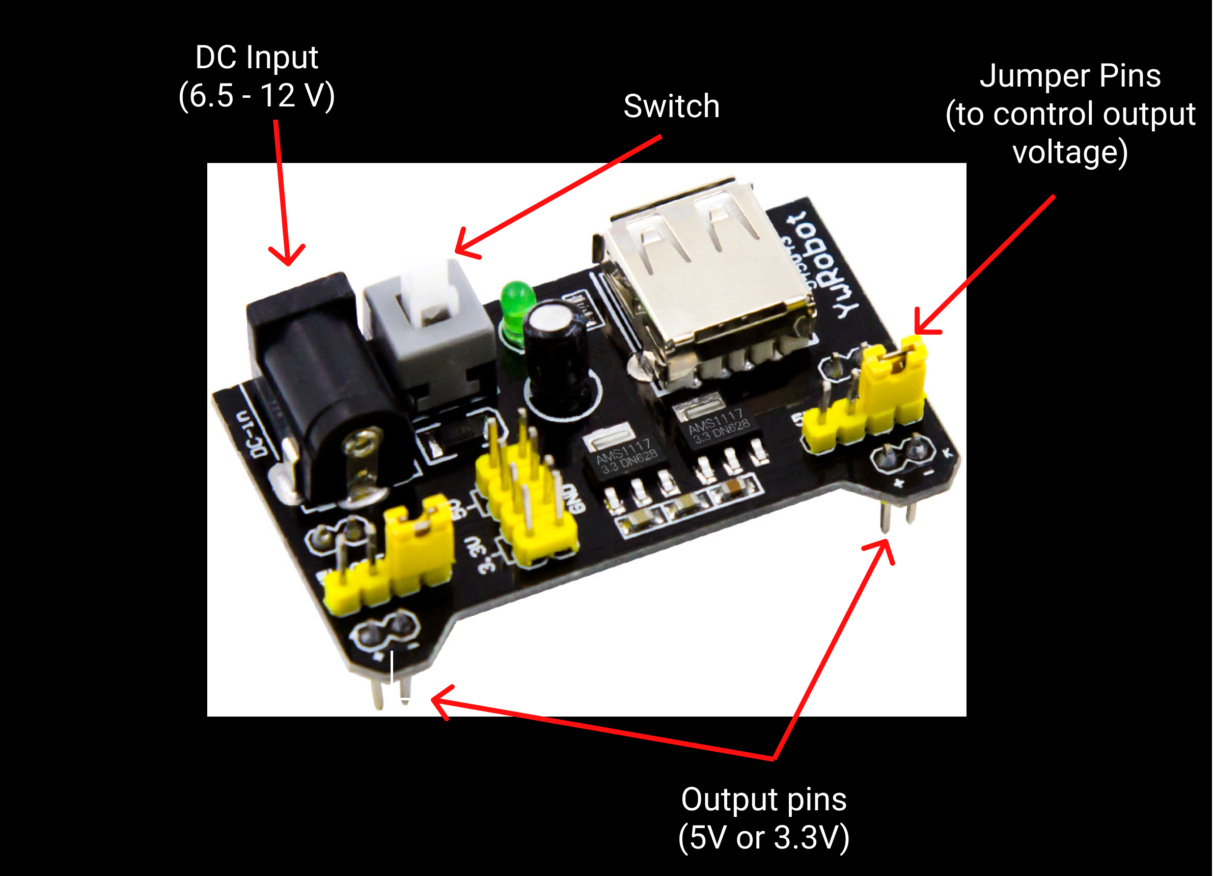
Breadboard power supply
The breadboard power supply can output 5V or 3.3V or both. There are 2 output pins and 2 jumper pins to set the configuration. It requires 6.5V–12V to function. If you are using both the pins, use the 12V input to deal with voltage drops. You can also power it using USB. There is a switch to turn on and off the device.
ESP8266 Node MCU (Microcontroller)
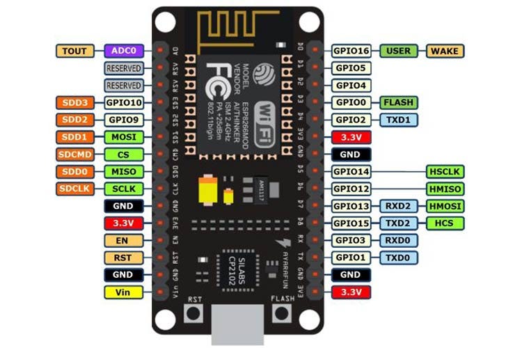
Source: Components101.com
There is a lot I can talk about when it comes to Node MCU, but I will stick to the details related to this project.
There are 16 GPIO pins in Node MCU, which can receive and send signals. Node MCU can communicate with other APIs and devices using WiFi. Node MCU required 3.3 V to power up and it can be done so using Micro-USB or Vin and GND pins. You can use pins from D1 to D8 to send signals to the relay board. We can use Arduino IDE to program Node MCU and use Blynk to send commands using our phone. We can then connect Blynk to IFTTT to connect it to Google Assistant.
Now, let’s hook them all up!
#diy #iot #programming #engineering #technology