Everything You Need to Know About Kubernetes Networking
Everything I learned about the Kubernetes Networking
An illustrated guide to Kubernetes Networking [Part 1]
You’ve been running a bunch of services on a Kubernetes cluster and reaping the benefits. Or at least, you’re planning to. Even though there are a bunch of tools available to setup and manage a cluster, you’ve still wondered how it all works under the hood. And where do you look if it breaks? I know I did.
Sure Kubernetes is simple enough to start using it. But let’s face it — it’s a complex beast under the hood. There are a lot of moving parts, and knowing how they all fit in and work together is a must, if you want to be ready for failures. One of the most complex, and probably the most critical parts is the Networking.
So I set out to understand exactly how the Networking in Kubernetes works. I read the docs, watched some talks, even browsed the codebase. And here is what I found out.
Kubernetes Networking Model
At it’s core, Kubernetes Networking has one important fundamental design philosophy:
Every Pod has a unique IP.
This Pod IP is shared by all the containers in this Pod, and it’s routable from all the other Pods. Ever notice some “pause” containers running on your Kubernetes nodes? They are called “sandbox containers”, whose only job is to reserve and hold a network namespace (netns) which is shared by all the containers in a pod. This way, a pod IP doesn’t change even if a container dies and a new one in created in it’s place. A huge benefit of this IP-per-pod model is there are no IP or port collisions with the underlying host. And we don’t have to worry about what port the applications use.
With this in place, the only requirement Kubernetes has is that these Pod IPs are routable/accessible from all the other pods, regardless of what node they’re on.
Intra-node communication
The first step is to make sure pods on the same node are able to talk to each other. The idea is then extended to communication across nodes, to the internet and so on.
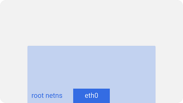
On every Kubernetes node, which is a linux machine in this case, there’s a root network namespace (root as in base, not the superuser) — root netns.
The main network interface eth0is in this root netns.
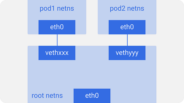
Similarly, each pod has its own netns, with a virtual ethernet pair connecting it to the root netns. This is basically a pipe-pair with one end in root netns, and other in the pod netns.
We name the pod-end eth0, so the pod doesn’t know about the underlying host and thinks that it has its own root network setup. The other end is named something like vethxxx.
You may list all these interfaces on your node using ifconfig or ip a commands.
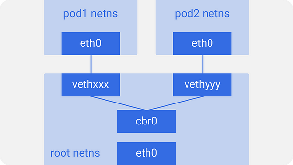
This is done for all the pods on the node. For these pods to talk to each other, a linux ethernet bridge cbr0 is used. Docker uses a similar bridge named docker0.
You may list the bridges using brctl show command.
Assume a packet is going from pod1 to pod2.
1. It leaves pod1’s netns at eth0 and enters the root netns at vethxxx.
2. It’s passed on to cbr0, which discovers the destination using an ARP request, saying “who has this IP?”
3. vethyyy says it has that IP, so the bridge knows where to forward the packet.
4. The packet reaches vethyyy, crosses the pipe-pair and reaches pod2’s netns.
This is how containers on a node talk to each other. Obviously there are other ways, but this is probably the easiest, and what docker uses as well.
Inter-node communication
As I mentioned earlier, pods need to be reachable across nodes as well. Kubernetes doesn’t care how it’s done. We can use L2 (ARP across nodes), L3 (IP routing across nodes — like the cloud provider route tables), overlay networks, or even carrier pigeons. It doesn’t matter as long as the traffic can reach the desired pod on another node. Every node is assigned a unique CIDR block (a range of IP addresses) for pod IPs, so each pod has a unique IP that doesn’t conflict with pods on another node.
In most of the cases, especially in cloud environments, the cloud provider route tables make sure the packets reach the correct destination. The same thing could be accomplished by setting up correct routes on every node. There are a bunch of other network plugins that do their own thing.
Here we have two nodes, similar to what we saw earlier. Each node has various network namespaces, network interfaces and a bridge.
Assume a packet is going from pod1 to pod4 (on a different node).
- It leaves
pod1’s netns ateth0and enters the root netns atvethxxx. - It’s passed on to
cbr0, which makes the ARP request to find the destination. - It comes out of
cbr0to the main network interfaceeth0since nobody on this node has the IP address forpod4. - It leaves the machine
node1onto the wire withsrc=pod1anddst=pod4. - The route table has routes setup for each of the node CIDR blocks, and it routes the packet to the node whose CIDR block contains the
pod4IP. - So the packet arrives at
node2at the main network interfaceeth0. - Now even though
pod4isn’t the IP ofeth0, the packet is still forwarded tocbr0since the nodes are configured with IP forwarding enabled. - The node’s routing table is looked up for any routes matching the
pod4IP. It findscbr0as the destination for this node’s CIDR block. - You may list the node route table using
route -ncommand, which will show a route forcbr0like this:
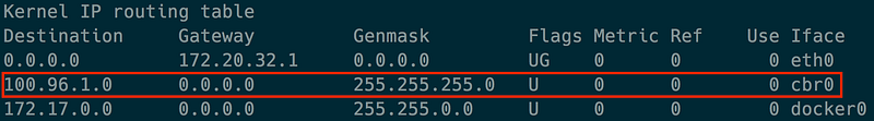
-
The bridge takes the packet, makes an ARP request and finds out that the IP belongs to
vethyyy. -
The packet crosses the pipe-pair and reaches
pod4🏠
An illustrated guide to Kubernetes Networking [Part 2]
We’ll expand on these ideas and see how the overlay networks work. We will also understand how the ever-changing pods are abstracted away from apps running in Kubernetes and handled behind the scenes.
Overlay networks
Overlay networks are not required by default, however, they help in specific situations. Like when we don’t have enough IP space, or network can’t handle the extra routes. Or maybe when we want some extra management features the overlays provide. One commonly seen case is when there’s a limit of how many routes the cloud provider route tables can handle. For example, AWS route tables support up to 50 routes without impacting network performance. So if we have more than 50 Kubernetes nodes, AWS route table won’t be enough. In such cases, using an overlay network helps.
It is essentially encapsulating a packet-in-packet which traverses the native network across nodes. You may not want to use an overlay network since it may cause some latency and complexity overhead due to encapsulation-decapsulation of all the packets. It’s often not needed, so we should use it only when we know why we need it.
To understand how traffic flows in an overlay network, let’s consider an example of flannel, which is an open-source project by CoreOS.
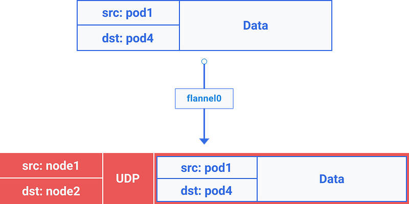
Here we see that it’s the same setup as before, but with a new virtual ethernet device called flannel0 added to root netns. It’s an implementation of Virtual Extensible LAN (VXLAN), but to linux, its just another network interface.
The flow for a packet going from pod1 to pod4 (on a different node) is something like this:
-
The packet leaves
pod1’s netns ateth0and enters the root netns atvethxxx. -
It’s passed on to
cbr0, which makes the ARP request to find the destination.
3a. Since nobody on this node has the IP address for pod4, bridge sends it to flannel0 because the node’s route table is configured with flannel0 as the target for the pod network range .
3b. As the flanneld daemon talks to the Kubernetes apiserver or the underlying etcd, it knows about all the pod IPs, and what nodes they’re on. So flannel creates the mappings (in userspace) for pods IPs to node IPs.
flannel0 takes this packet and wraps it in a UDP packet with extra headers changing the source and destinations IPs to the respective nodes, and sends it to a special vxlan port (generally 8472).
Even though the mapping is in userspace, the actual encapsulation and data flow happens in kernel space. So it happens pretty fast.
3c. The encapsulated packet is sent out via eth0 since it is involved in routing the node traffic.
-
The packet leaves the node with node IPs as source and destination.
-
The cloud provider route table already knows how to route traffic between nodes, so it send the packet to destination
node2.
6a. The packet arrives at eth0 of node2. Due to the port being special vxlan port, kernel sends the packet to flannel0.
6b. flannel0 de-capsulates and emits it back in the root network namespace.
6c. Since IP forwarding is enabled, kernel forwards it to cbr0 as per the route tables.
-
The bridge takes the packet, makes an ARP request and finds out that the IP belongs to
vethyyy. -
The packet crosses the pipe-pair and reaches
pod4🏠
There could be slight differences among different implementations, but this is how overlay networks in Kubernetes work. There’s a common misconception that we have to use overlays when using Kubernetes. The truth is, it completely depends on the specific scenarios. So make sure you use it only when it’s absolutely needed.
An illustrated guide to Kubernetes Networking [Part 3]
Cluster dynamics
Due to the every-changing dynamic nature of Kubernetes, and distributed systems in general, the pods (and consequently their IPs) change all the time. Reasons could range from desired rolling updates and scaling events to unpredictable pod or node crashes. This makes the Pod IPs unreliable for using directly for communications.
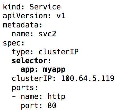
Enter Kubernetes Services — a virtual IP with a group of Pod IPs as endpoints (identified via label selectors). These act as a virtual load balancer, whose IP stays the same while the backend Pod IPs may keep changing.
The whole virtual IP implementation is actually iptables (the recent versions have an option of using IPVS, but that’s another discussion) rules, that are managed by the Kubernetes component — kube-proxy. This name is actually misleading now. It used to work as a proxy pre-v1.0 days, which turned out to be pretty resource intensive and slower due to constant copying between kernel space and user space. Now, it’s just a controller, like many other controllers in Kubernetes, that watches the api server for endpoints changes and updates the iptables rules accordingly.
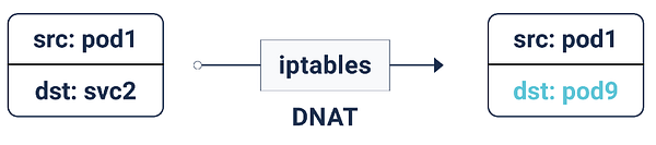
Due to these iptables rules, whenever a packet is destined for a service IP, it’s DNATed (DNAT=Destination Network Address Translation), meaning the destination IP is changed from service IP to one of the endpoints — pod IP — chosen at random by iptables. This makes sure the load is evenly distributed among the backend pods.
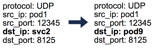
When this DNAT happens, this info is stored in conntrack — the Linux connection tracking table (stores 5-tuple translations iptables has done: protocol, srcIP, srcPort, dstIP, dstPort). This is so that when a reply comes back, it can un-DNAT, meaning change the source IP from the Pod IP to the Service IP. This way, the client is unaware of how the packet flow is handled behind the scenes.
So by using Kubernetes services, we can use same ports without any conflicts (since we can remap ports to endpoints). This makes service discovery super easy. We can just use the internal DNS and hard-code the service hostnames. We can even use the service host and port environment variables preset by Kubernetes.
Protip: Take this second approach and save a lot of unnecessary DNS calls!
Outbound traffic
The Kubernetes services we’ve talked about so far work within a cluster. However, in most of the practical cases, applications need to access some external api/website.
Generally, nodes can have both private and public IPs. For internet access, there is some sort of 1:1 NAT of these public and private IPs, especially in cloud environments.
For normal communication from node to some external IP, source IP is changed from node’s private IP to it’s public IP for outbound packets and reversed for reply inbound packets. However, when connection to an external IP is initiated by a Pod, the source IP is the Pod IP, which the cloud provider’s NAT mechanism doesn’t know about. It will just drop packets with source IPs other than the node IPs.
So we use, you guessed it, some more iptables! These rules, also added by kube-proxy, do the SNAT (Source Network Address Translation) aka IP MASQUERADE. This tells the kernel to use IP of the interface this packet is going out from, in place of the source Pod IP. A conntrack entry is also kept to un-SNAT the reply.
Inbound traffic
Everything’s good so far. Pods can talk to each other, and to the internet. But we’re still missing a key piece — serving the user request traffic. As of now, there are two main ways to do this:
NodePort/Cloud Loadbalancer (L4 — IP and Port) Setting the service type to NodePort assigns the service a nodePort in range 30000-33000. This nodePort is open on every node, even if there’s no pod running on a particular node. Inbound traffic on this NodePort would be sent to one of the pods (it may even be on some other node!) using, again, iptables.
A service type of LoadBalancer in cloud environments would create a cloud load balancer (ELB, for example) in front of all the nodes, hitting the same nodePort.
Ingress (L7 — HTTP/TCP)
A bunch of different implements, like nginx, traefik, haproxy, etc., keep a mapping of http hostnames/paths and the respective backends. This is entry point of the traffic over a load balancer and nodeport as usual, but the advantage is that we can have one ingress handling inbound traffic for all the services instead of requiring multiple nodePorts and load balancers.
Network Policy
Think of this like security groups/ACLs for pods. The NetworkPolicy rules allow/deny traffic across pods. The exact implementation depends on the network layer/CNI, but most of them just use iptables.
That’s all for now. In the previous parts we studied the foundation of Kubernetes Networking and how overlays work. Now we know how the Service abstraction helping in a dynamic cluster and makes discovery super easy. We also covered how the outbound and inbound traffic flow works and how network policy is useful for security within a cluster.
#kubernetes #devops #developer